CAN FD vs Classical CAN: A Practical Trade-off Table
CAN FD doubles the data phase bitrate and extends the payload to 64 bytes. The transceiver choice and EMC implications follow from those two facts in non-obvious ways.
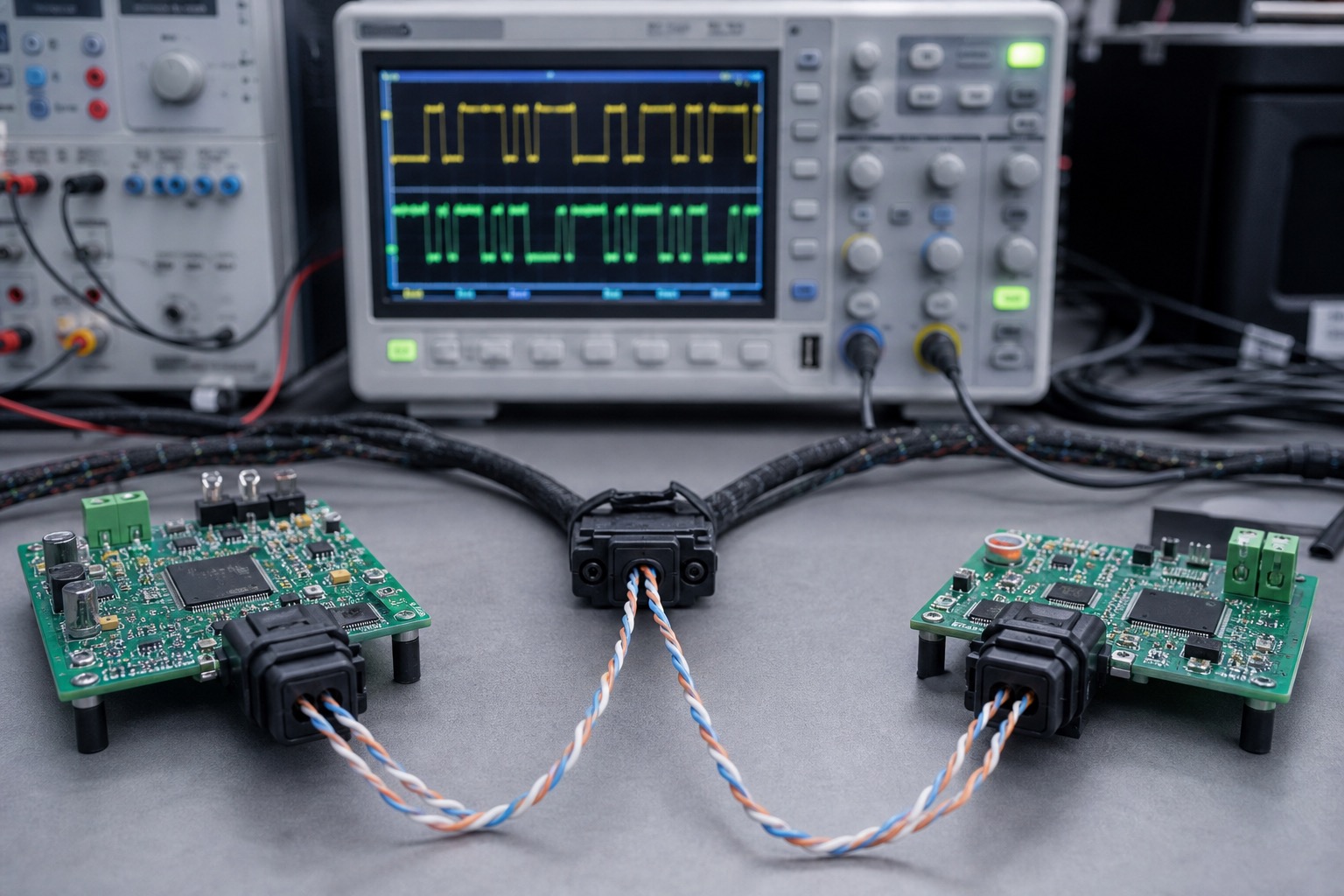
CAN FD doubles the data phase bitrate and extends payload to 64 bytes. Those two facts drive transceiver selection, termination, EMC testing, and backward compatibility decisions that datasheets scatter across footnotes. This is a practical trade-off table from a project that shipped classical CAN first and migrated one subnet to FD.
Hardware bring-up reference: CAN bus node on STM32G0. Power delivery tangents: USB-C PD confusion notes.
Spec delta in one paragraph
Classical CAN (ISO 11898-1): max 8 data bytes, arbitration and data phase at same bitrate (typically 125k–1 Mbit/s).
CAN FD (ISO 11898-1:2015): arbitration phase at classical rate, data phase at higher rate (up to 8 Mbit/s data phase on some transceivers), up to 64 bytes payload, BRS bit switches phases, optional stuff bit count for CRC.
You cannot drop FD frames on a classical-only bus without protocol bridges — mixed networks require FD-capable nodes on the FD segment.
Trade-off table
| Factor | Classical CAN | CAN FD | Notes |
|---|---|---|---|
| Max payload | 8 bytes | 64 bytes | FD reduces frame count for bulk data |
| Bitrate | Single | Arbitration + data | EMI peaks in data phase |
| Transceiver | MCP2551, TJA1050, SN65HVD230 | TJA1043, TCAN1042, SN65HVD265 | FD needs rated data phase speed |
| MCU IP | bxCAN | FDCAN / M_CAN | STM32G4, H7, many G0 with FDCAN |
| Wire length @ 1 Mbit/s | ~40 m (rule of thumb) | Arbitration 1M, data 5M shortens margin | Recalculate sample points |
| Software stack | Mature, simple | Complex filters, buffer sizing | Autosar stacks $$ |
| Debug tools | Any CAN adapter | Need FD-capable adapter | PCAN-USB FD ~$300 |
| Backward compat | Baseline | FD nodes talk classical to classic nodes | Format matters |
| EMC | Lower peak frequency | Higher dv/dt in data phase | Filter + layout critical |
When classical CAN is still correct
- All payloads fit in 8 bytes with margin (automotive signals, sensors)
- Bus length > 30 m at required speed
- Ecosystem is legacy controllers (no firmware update path)
- Cert body approved classical design — re-cert FD costs calendar
I kept classical on a 40 m agricultural sensor bus at 250 kbit/s. FD gain was zero; transceiver swap risk was non-zero.
When FD pays off
- Firmware updates over bus (OTA chunks)
- Diagnostics dumps > 8 bytes without fragmentation
- Same physical harness, need throughput — data phase at 2 Mbit/s while keeping 500 kbit/s arbitration for legacy ECU coexistence
Project example: industrial controller sent 48-byte telemetry at 10 Hz. Classical CAN required 6 frames per sample with sequencing overhead. FD: one frame, CPU load dropped 40% on the gateway MCU.
Transceiver selection detail
SN65HVD230 — classical, 1 Mbit/s. Do not use for FD data phase at 2 Mbit/s even if "it seemed to work" on bench.
TCAN1042V (TI) — FD up to 5 Mbit/s data, 3.3 V IO, standby mode. My default for new designs.
Termination: Still 120 Ω differential, but check cable impedance at data phase harmonics. Cheap flat cable failed EMC at 5 Mbit/s data; twisted pair 120 Ω nominal passed.
Common mode choke: Often required for FD at 2 Mbit/s+ on long runs. Classical designs skipped choke; FD radiated emissions failed CISPR 25 without.
Bit timing: two sample points
FD requires separate timing for arbitration and data phases:
Arbitration: 500 kbit/s, sample point ~75–80%
Data:        2 Mbit/s, sample point ~70–75% (vendor-specific guidance)
STM32 FDCAN CubeMX configures NominalPrescaler vs DataPrescaler. Wrong data phase timing → error frames only at BRS transition — classic scope-debug nightmare.
Capture with CAN FD analyzer on the BRS edge — look for bit errors starting exactly when phase switches.
Software buffer implications
64-byte payload + FD headers → larger RX FIFO requirements. On STM32H7 FDCAN, I doubled RxFifo0ElmtsNbr vs classical project.
ISO-TP over FD exists but stack support varies. Verify your bootloader (MCUboot, etc.) speaks FD if you OTA over CAN.
Migration strategy that worked
- Ship new nodes FD-capable, classical-only firmware first
- Validate bus with classical frames — same IDs, 8-byte payloads
- Enable FD on gateway only; send FD test frames on maintenance ID
- Roll FD payloads per message after EMC re-test on FD segment
Do not flip entire fleet at once.
EMC finding worth repeating
FD data phase at 2 Mbit/s on unshielded harness parallel to motor power cable: conducted emissions failed 150 kHz–30 MHz band by 8 dB. Fixes applied (in order of cost):
- Move harness routing (free)
- Common mode choke on FD nodes ($0.40 BOM)
- Shielded twisted pair ($)
Classical on same routing passed. FD is not plug-compatible with classical EMC assumptions.
Cost snapshot
| Item | Classical | FD |
|---|---|---|
| Transceiver | $0.80 | $1.20 |
| MCU with FDCAN | $3.50 (G0) | $4.50 (G0 FD) |
| Analyzer | $25 CANable | $80 CANable FD |
| EMC retest | baseline | +$3k lab time |
What I would decide today
New design, greenfield subnet, payloads > 8 bytes or firmware OTA: FD from day one with FD-rated transceiver and analyzer.
Brownfield with 15-year harness and 500 kbit/s classical: stay classical until a throughput metric fails.
Mixed: gateway pattern — FD backbone, classical stubs via translator MCU.
Related
STM32G0 CAN bring-up for classical first frame. USB-C PD notes if power and data share a connector in your product.

Manish Bookreader
Electronics enthusiast, Embedded Systems Expert, Linux/Networking programmer, and Software Engineer passionate about AI, electronics, books, and cooking.