CAN Bus Node With STM32G0: From Transceiver Selection to First Frame
CAN is well-specified and badly documented for newcomers. A complete walkthrough of hardware selection, bxCAN configuration, and sending a first frame on STM32G0B1.
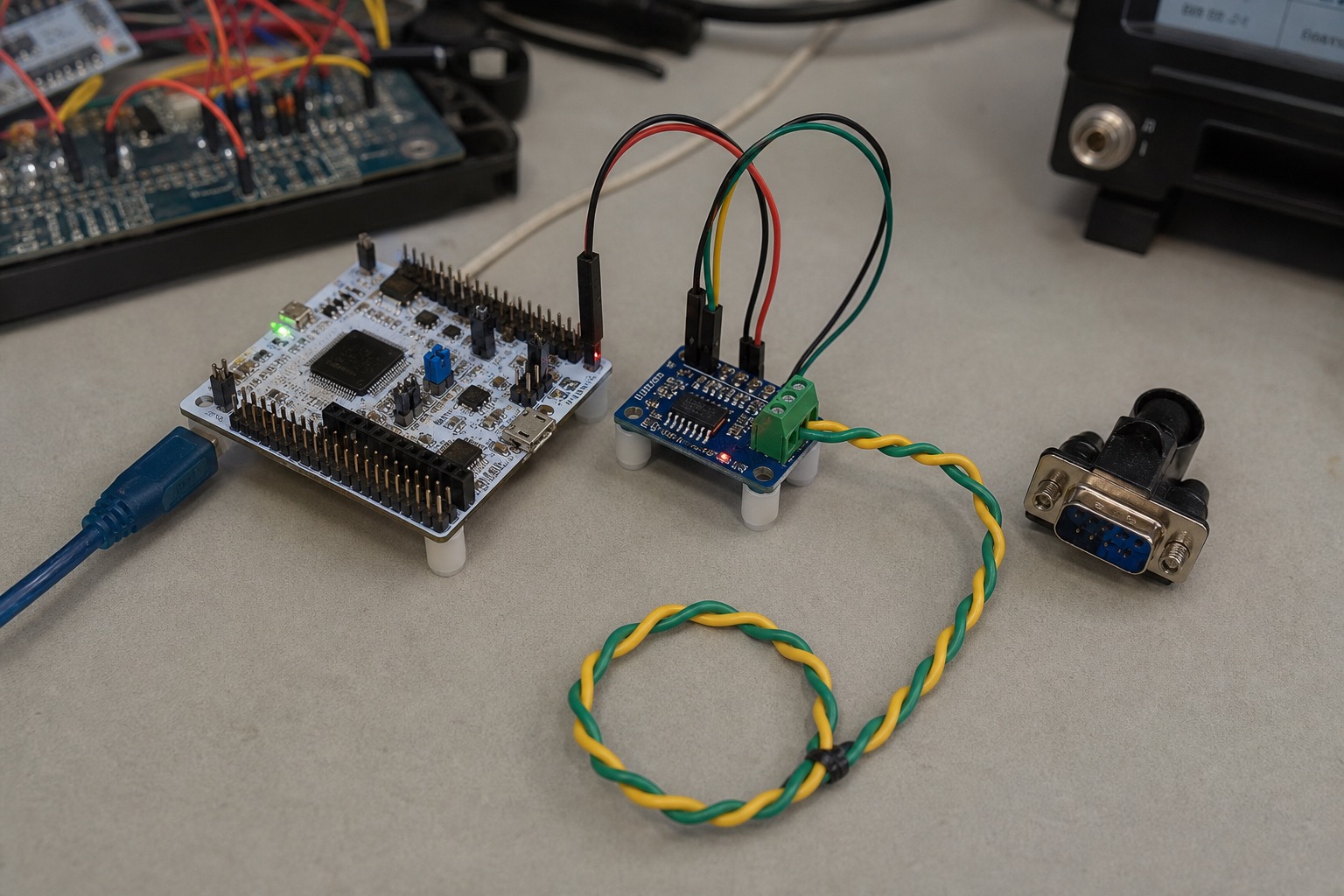
CAN is well-specified in ISO 11898 and badly explained in most MCU vendor app notes. This walkthrough takes an STM32G0B1 from zero to a transmitted standard frame on a real bus, including transceiver selection, bit timing, filter configuration, and the mistakes that cost me a day on a scope.
Related debugging paths: SPI bus debugging notes, logic analyzer I2C glitches.
Target hardware
| Component | Part | Why |
|---|---|---|
| MCU | STM32G0B1RE Nucleo-64 | bxCAN, cheap, 512 KB flash |
| Transceiver | TI SN65HVD230DR | 3.3 V, slope control pin, automotive common |
| Termination | 120 Ω, switchable | One end only for bench loopback |
| Analyzer | PEAK PCAN-USB or cheap CANable | Verify frames independently |
SN65HVD230 vs MCP2551: both work at 3.3 V IO if VIO pin tied correctly on 230. MCP2551 is 5 V logic — fine with G0 if you tolerate level mismatch on RX or add level shifter. I standardize on 230 for 3.3 V MCUs.
Wiring (do this before code)
MCU PB8  (CAN_RX) <-- CANH/CANL via transceiver RXD
MCU PB9  (CAN_TX) --> transceiver TXD
Transceiver RS pin --> GND (high speed mode) or 3.3 V (slope control low)
120 Ω between CANH and CANL at ONE node only
Common failure: two terminators on a two-node bench setup attenuates signal. One terminator.
Another failure: CANH/CANL swapped. Transceiver survives; bus does not talk.
Clock and bit timing
STM32G0 CAN clock comes from APB1. On Nucleo-G0B1RE with default HSE/PLL config, APB1 often runs at 64 MHz. You need a bitrate prescaler and time quanta that hit 500 kbit/s (common automotive) or 250 kbit/s (industrial).
Formula:
Bitrate = F_CAN_clock / (Prescaler × (1 + BS1 + BS2))
Sample point ≈ (1 + BS1) / (1 + BS1 + BS2)
Target for 500 kbit/s at 64 MHz CAN clock:
Prescaler = 8
BS1 = 13 TQ
BS2 = 2 TQ
SJW = 1 TQ
→ 64 MHz / (8 × 16) = 500 kbit/s
Sample point = 14/16 = 87.5%
CubeMX calculates this if you enable FDCAN/CAN and set bitrate — verify the register dump. I have seen CubeMX pick 87.5% sample point that fails on a long bus with slow transceivers. Bench is short; production bus may not be.
Register-level sanity check in main() after init:
/* Expected: BTR register consistent with 500 kbit/s */
uint32_t btr = READ_REG(hcan.Instance->BTR);
CubeMX / HAL init checklist
- Enable CAN1, PB8/PB9 AF mapping
- Bitrate 500 kbit/s, mode normal (not loopback yet)
- Auto retransmission enabled
- Receive FIFO0 interrupt optional for this test
Generate code, but do not trust generated filter defaults for production. For transmit-only bring-up, filters can accept all.
Minimal filter config (accept all → FIFO0)
CAN_FilterTypeDef filter = {0};
filter.FilterBank = 0;
filter.FilterMode = CAN_FILTERMODE_IDMASK;
filter.FilterScale = CAN_FILTERSCALE_32BIT;
filter.FilterIdHigh = 0x0000;
filter.FilterIdLow = 0x0000;
filter.FilterMaskIdHigh = 0x0000;
filter.FilterMaskIdLow = 0x0000;
filter.FilterFIFOAssignment = CAN_FILTER_FIFO0;
filter.FilterActivation = ENABLE;
HAL_CAN_ConfigFilter(&hcan, &filter);
Production code narrows this — promiscuous mode hides filter bugs until field deploy.
Start sequence (order matters)
HAL_CAN_ConfigFilter(&hcan, &filter);
HAL_CAN_Start(&hcan);
HAL_CAN_ActivateNotification(&hcan, CAN_IT_RX_FIFO0_MSG_PENDING);

CAN_TxHeaderTypeDef txHeader = {0};
uint8_t txData[8] = {0x11, 0x22, 0x33, 0x44, 0x55, 0x66, 0x77, 0x88};
uint32_t txMailbox;

txHeader.StdId = 0x123;
txHeader.IDE = CAN_ID_STD;
txHeader.RTR = CAN_RTR_DATA;
txHeader.DLC = 8;
txHeader.TransmitGlobalTime = DISABLE;

HAL_CAN_AddTxMessage(&hcan, &txHeader, txData, &txMailbox);
If HAL_CAN_AddTxMessage returns HAL_ERROR, check:
HAL_CAN_Startwas called- Bus is not in bus-off (ESR register LEC field)
- At least one other node acknowledges — CAN requires ACK
The ACK problem on a bench
CAN is not UART. A transmitted frame must be ACK'd by any receiver on the bus. Solo node with no analyzer listening → transmit error counter increments → bus-off.
Minimum bench setup: your node + USB-CAN adapter configured to same bitrate, terminated correctly, listening.
Loopback mode (HAL_CAN_Init parameter) verifies MCU only — use for first smoke test, then disable for real bus.
Verification with PCAN-View
Expected frame:
- ID: 0x123 standard
- DLC: 8
- Data: 11 22 33 44 55 66 77 88
If you see error frames instead:
- Bitrate mismatch (most common)
- Missing termination
- Dominant stuck (transceiver short)
Scope on CANH-CANL differential: clean square-ish 2 V peak at 500 kbit/s. Rounded edges often mean wrong RS pin on SN65HVD230.
bxCAN vs FDCAN on G0
STM32G0B1 has FDCAN, not classical bxCAN on some parts — check your exact part number. Nucleo-G0B1RE uses FDCAN in newer CubeMX packs. API differs slightly (FDCAN_TxHeaderTypeDef). This note describes bxCAN pattern; for G0B1 FDCAN:
- Enable ISO mode for classical CAN compatibility
- Set
FrameFormat = FDCAN_FRAME_CLASSIC - DataLengthCode maps to DLC
I wasted four hours mixing bxCAN tutorial code with FDCAN silicon. Match the reference manual for your specific STM32G0B1xx.
Error handling worth adding early
Read ESR (Error Status Register) in a debug UART print:
uint32_t esr = hcan.Instance->ESR;
uint8_t lec = (esr >> 4) & 0x7;  /* Last Error Code */
uint8_t tec = (esr >> 16) & 0xFF; /* Tx Error Counter */
uint8_t rec = (esr >> 24) & 0xFF; /* Rx Error Counter */
LEC codes 1–7 tell you bit vs stuff vs ACK vs form error. Do not printf in ISR — poll in main loop during bring-up.
Next steps after first frame
- Configure acceptance filter for ID 0x100–0x1FF only
- Add RX interrupt handler, echo frame
- Measure bus load if sending periodic frames
- Read CAN FD vs classical trade-offs before committing to FD transceivers
BOM for a two-node bench
| Qty | Part |
|---|---|
| 1 | Nucleo-G0B1RE |
| 1 | SN65HVD230 breakout |
| 1 | CANable 2.0 or PEAK adapter |
| 2 | 120 Ω 1% resistors (use one) |
| 1 | Twisted pair, short |
Total under $80 if you already own the Nucleo.
What I would do differently
Start with loopback mode for 15 minutes, then switch to real bus with analyzer already running. I debugged "broken TX" for hours with no ACK source.
Buy the CANable before writing filter code. Seeing your frames externally is non-negotiable.

Manish Bookreader
Electronics enthusiast, Embedded Systems Expert, Linux/Networking programmer, and Software Engineer passionate about AI, electronics, books, and cooking.