SPI Bus Debugging: When CPOL/CPHA Gets You at 3 AM
Clock polarity and phase mismatches are boring until your sensor returns all-zeros at midnight during bring-up. A systematic approach to sorting it out fast.
Clock polarity and phase mismatches are boring until your sensor returns all-zeros at midnight during bring-up. A systematic approach to sorting it out fast — before you swap the ADC for the third time.
Answer first
Verify mode 0/1/2/3 against the datasheet timing diagram, not the driver's enum name. Capture CS, SCK, MOSI, MISO on four channels. First transaction after CS assert is ground truth. Fix CPOL/CPHA in firmware before touching layout unless MISO setup time violates spec at your SCK rate.
The 3 AM scenario
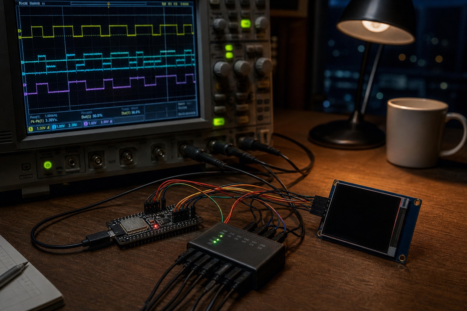
LIS2MDL magnetometer on SPI — supposed to return 0x40 on WHO_AM_I. Scope showed clean clocks, CS timed correctly, MISO flat low. Driver read 0x00. Git blame showed CPOL/CPHA changed in a "cleanup" commit six weeks prior. Sensor never tested on that branch until integration freeze.
CPOL/CPHA in one paragraph
- CPOL = idle clock level (0 = low idle, 1 = high idle)
- CPHA = which edge samples (0 = first edge, 1 = second edge)
Datasheets use Mode 0–3 tables. ST HAL uses SPI_POLARITY_LOW/HIGH + SPI_PHASE_1EDGE/2EDGE. Silicon Labs uses different naming. Always draw the first four edges.
Systematic bring-up checklist
1. Wire order (logic analyzer)
| Ch | Signal |
|---|---|
| 0 | CS |
| 1 | SCK |
| 2 | MOSI |
| 3 | MISO |
Sample rate ≥ 10× SCK. For 10 MHz SPI, 24 MHz LA minimum; scope preferred for analog SI.
Use oscilloscope triggers on CS rising edge, holdoff > one frame period.
2. Mode sweep (automated)
Script on bench Raspberry Pi or MCU test firmware:
for (mode = 0; mode < 4; mode++) {
  spi_configure(cpol_cpha[mode]);
  id = read_reg(WHO_AM_I);
  log("%d: 0x%02x", mode, id);
}
Expect exactly one mode matches datasheet. If zero match: wiring, voltage, or dead chip — not mystery drift.
3. Timing numbers from datasheet
Check:
fSCK maxtSU(MISO)setup before capture edgetH(MISO)hold after capture edge- CS setup/hold to first SCK edge
Violating setup at 20 MHz on 30 cm dupont wires is normal. Drop to 1 MHz for ID read; optimize later.
4. Full-duplex vs. half-duplex
Reading WHO_AM_I often requires simultaneous clocking while sending command byte — SPI_TransmitReceive not Receive alone. HAL users: HAL_SPI_Receive without TX sometimes clocks zeros on MOSI while slave expects command on first byte — MISO garbage that looks like mode mismatch.
5. DMA vs. polled first
Get polled single-byte Xfer working before DMA double-buffer. See STM32H7 DMA double-buffer issues — DMA masks timing bugs until scale.
Failure modes beyond CPOL/CPHA
| Symptom | Likely cause |
|---|---|
0xFF always | MISO floating / wrong pin mux |
| Correct ID, wrong data | byte order (MSB first assumed) |
| Intermittent wrong bits | SI on MISO, long stub, no series R |
| Shifted bit pattern | 9-bit SPI mode (Parity) enabled by mistake |
| Works slow, fails fast | setup time; or cache coherency on H7 with DMA |
Compare with I2C failure fingerprints — stuck-high bus vs. SPI's tri-state MISO difference.
Hardware notes
- Series 22–33 Ω on SCK/MOSI near master — damp overshoot.
- MISO pull-up: usually don't — many slaves actively drive; check if device requires pull on CS deassert.
- Shared SPI bus: verify CS idle high, no crosstalk on MISO when other slave selected (tristate leak).
Tooling
- Saleae SPI analyzer — set signifiance: MSB, bits per transfer, CPOL/CPHA match sweep result.
flashrom-style bitbang on Pi — slow gold reference when MCU suspect.
Ship log entry
Product: gas sensor front-end, ADXL355 + AD5693 on shared SPI @ 8 MHz. Mode 3 confirmed. Production failure 0.3% — MISO ring on layout via shared via with AGND return. Fixed in rev B with dedicated MISO route + 33 Ω. Mode was never wrong; SI was.
Lesson: run mode sweep once, then spend remaining time on SI and driver semantics.
What I'd do next
Add WHO_AM_I mode sweep to factory test fixture — 200 ms per board, catches CPOL/CPHA regressions and dead solder on MISO. Log pass mode to EEPROM for traceability.
Document per-slave mode in device tree / board.h — never inherit global SPI bus default without comment.
Logic analyzer decode gotchas
Saleae SPI analyzer defaults MSB first — matches most MEMS. Some TI ADCs document LSB-first on control words only — split transactions in analyzer if needed.
Set significant bits to match actual transfer width. 16-bit register read as 8-bit streams mis-decodes as two bogus bytes — looks like CPOL wrong when it's width wrong.
Daisy chain and multiple CS
Shared SCK/MOSI/MISO with separate CS — decode per CS channel. Trigger on CS0 rising; verify CS1 idle high during transaction. Crosstalk on MISO when CS1 tristate leaks shows as ghost bits — rev B added 1 MΩ bleed on CS lines per layout review, not SPI mode change.
Factory fixture snippet
Our fixture runs mode sweep in 180 ms:
for mode in range(4):
    dut.set_spi_mode(mode)
    id = dut.read_reg(WHO_AM_I)
    log.append((mode, id))
assert expected_id in [x[1] for x in log]
Fails board before RF test — saves 12 min per bad unit.
What I'd do next

Manish Bookreader
Electronics enthusiast, Embedded Systems Expert, Linux/Networking programmer, and Software Engineer passionate about AI, electronics, books, and cooking.