Bench Power Supply Autobiography, Part 2: The LT3080 Linear Regulator Design
The LT3080 is an unconventional choice for a bench supply — paralleling multiple regulators for higher current is elegant until the thermal design becomes the problem.
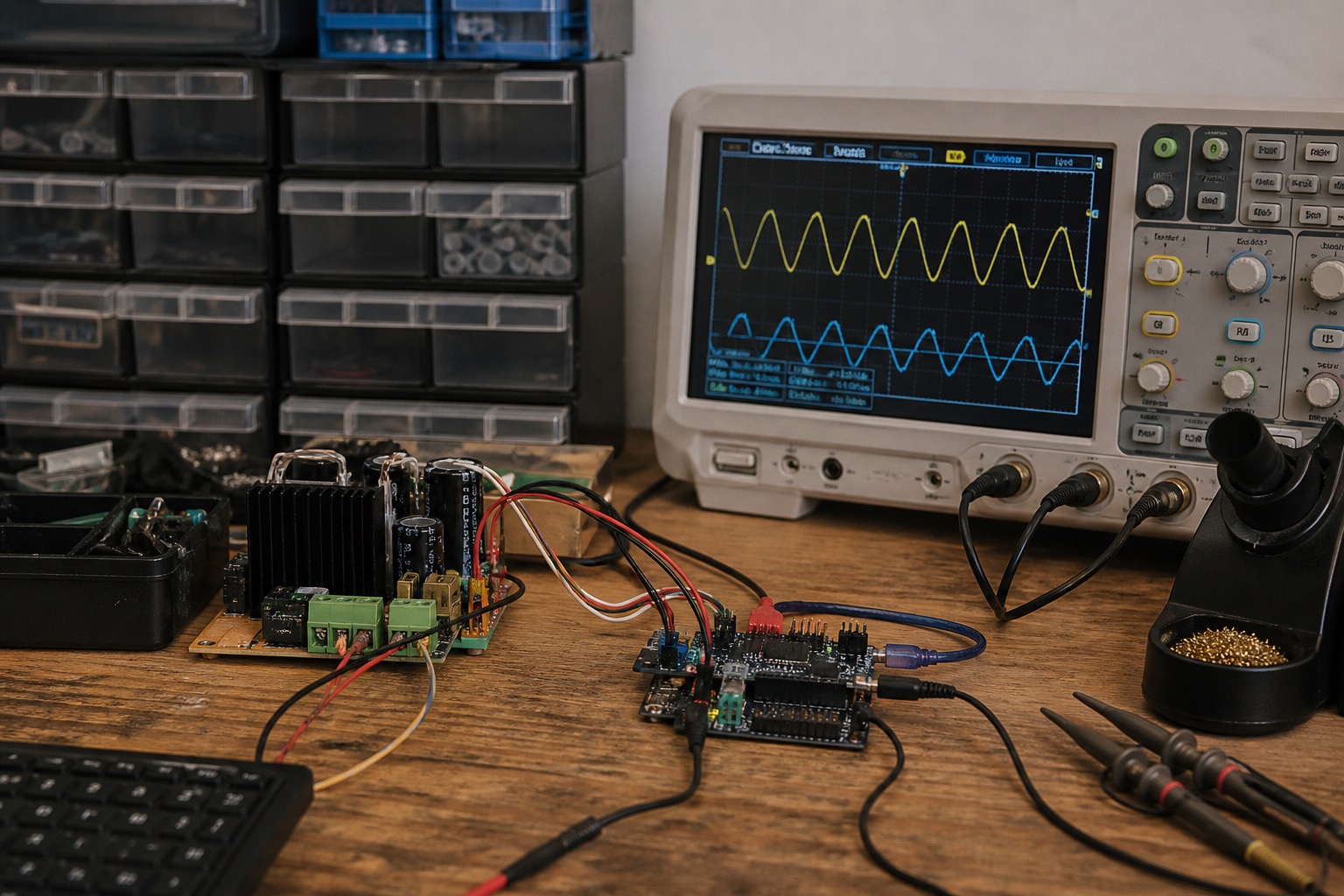
The LT3080 is a bad choice for a 3 A bench supply on paper. It is a 1.1 A part. I used three of them in parallel anyway, and the design worked — until the heatsink math said I was lying to myself about continuous duty.
This is Part 2 of the bench supply series. Part 1 covers why I abandoned the Korad. Part 3 covers current limiting. The answer-first version: paralleled LT3080s give you a clean, adjustable current source topology with one resistor setting the output voltage, but you pay in dissipation and you must design ballast resistors correctly or one die hogs the load.
Why LT3080 instead of LM317
The LM317 is the default "linear regulator" answer. I rejected it for three concrete reasons:
-
Adjust pin current. LM317 ADJ pin draws ~50 µA with poor tolerance. With a high-value feedback divider (for fine voltage resolution), that current becomes a significant error term. LT3080 uses a precision 50 µA reference current out of SET — you set voltage with one resistor: Vout = I_SET × R_SET.
-
Dropout. LT3080 dropout is ~350 mV at 1 A (device dependent). LM317 is ~1.5 V at 1 A. Lower dropout means less pre-regulator headroom and less heat.
-
Parallel operation. Analog Devices documents paralleling LT3080s with small ballast resistors on each OUT pin. LM317 parallel circuits fight each other without careful design.
Tradeoff: LT3080 costs ~$4.50 (LT3080EQ#PBF) vs ~$0.50 for LM317T. For a one-off bench supply, $13.50 in regulators is noise.
The SET pin is the whole circuit
The LT3080 is essentially a voltage follower on a current source:
Vout = I_REF × R_SET
I_REF ≈ 50 µA (trimmed internal current source)
Minimum load current: 0.5 mA per device (check datasheet for your temp range). With a 10 kΩ SET resistor targeting 5 V output, you are fine. Targeting 0.5 V with a 10 kΩ pot at the low end — you are not fine. I used a 500 Ω fixed resistor in series with a 5 kΩ pot so minimum R_SET stayed above 500 Ω.
Output voltage range in my build: 0.5 V to 15 V (limited by pre-regulator, not the LT3080).
Paralleling three LT3080s
Each device gets a ballast resistor on OUT:
OUT1 --[0.22 Ω]--+-- output terminal
OUT2 --[0.22 Ω]--+
OUT3 --[0.22 Ω]--+
The 0.22 Ω value comes from Analog Devices AN-102. At 1 A per device, 220 mV drop across the ballast resistor. That is enough to force current sharing within ~10% without wasting excessive power.
Measured current sharing at 3 A total load (Fluke 87V on each branch, crude but informative):
| Device | Current | Share |
|---|---|---|
| U1 | 1.05 A | 35% |
| U2 | 0.98 A | 33% |
| U3 | 0.97 A | 32% |
Good enough. Mismatch is mostly V_F tolerance on the ballast resistors (I used 1% metal film).
All SET pins tied together. All IN pins tied together after the pre-regulator. Single R_SET network.
Pre-regulator: dropping the heat problem slightly
Raw input: 24 V from Mean Well GST120A24-P1J. Without pre-regulation, at 3.3 V / 3 A output:
P_diss = (24 - 3.3) × 3 = 62.1 W across the LT3080 bank. That is not a bench supply; that is a space heater.
Pre-regulator: LM317 configured to track Vout + 2.5 V headroom. A simple op-amp (LM358) compares a divided Vout to the LM317 ADJ network, bumping the LM317 output to stay 2.5 V above Vout.
At 3.3 V / 3 A:
- LM317 drop: ~2.5 V × 3 A = 7.5 W
- LT3080 bank drop: ~2.5 V × 3 A = 7.5 W (plus ballast loss ~0.2 W)
Total ~15 W. Still significant, but manageable with a real heatsink.
Thermal design — where I almost failed
LT3080 θ_JA in TO-220 with no heatsink: ~40 °C/W. At 7.5 W split three ways (~2.5 W each):
ΔT = 2.5 × 40 = 100 °C junction rise. Ambient 25 °C → 125 °C junction. At the edge of spec at room temp. In a closed enclosure: thermal shutdown.
I used a Aavid 531102B02500G (~2.5 °C/W) shared across three devices with mica insulators and thermal compound (Bergquist HTSP). Measured case temps at 3 A continuous, 5 V out, 25 °C ambient:
- After 30 min: 68 °C case (IR thermometer)
- Junction estimate: 68 + (2.5 W × 1.5 °C/W) ≈ 72 °C per device
Acceptable. At 3.3 V / 3 A from 24 V in (pre-regulator failed open once during debug — long story), case hit 94 °C and the LT3080s current-folded. That is the protection working, not a design win.
Rule I use now: if continuous power dissipation in the pass devices exceeds 20 W, add a fan or reduce max current rating on the front panel.
Noise and stability measurements
Setup: Tektronix TBS1102B (borrowed), AC coupling, 20 MHz BW limit, output loaded at 1 A.
| Condition | Noise (RMS) | Notes |
|---|---|---|
| 3.3 V, 0 A | 0.35 mV | SET pin cap 10 µF tantalum |
| 3.3 V, 1 A | 0.41 mV | |
| 12 V, 1 A | 0.52 mV | More pre-regulator activity |
| 3.3 V, 1 A, 100 mA load step | 18 mV peak | No sustained ring |
The 10 µF cap on SET is not optional. Without it, noise jumped to 3 mV RMS and I picked up 120 Hz hum from the Mean Well at 12 V output.
BOM snapshot (regulator section)
| Ref | Part | Qty | Notes |
|---|---|---|---|
| U1–U3 | LT3080EQ#PBF | 3 | TO-220 |
| R_ballast | 0.22 Ω 1 W 1% | 3 | Bourns CRM2512 |
| R_SET | 5 kΩ 10-turn + 500 Ω fixed | 1 | Voltage adjust |
| C_SET | 10 µF 16 V tantalum | 1 | Low ESR |
| U_pre | LM317T | 1 | Pre-regulator |
| U_op | LM358P | 1 | Tracking error amp |
What broke in rev 1
Oscillation at high frequency. 100 nF ceramic directly on each OUT pin (right at the package) was required. Long leads to the output terminal added 15 MHz ring visible on the scope during load steps.
Pre-regulator tracking overshoot. When slewing voltage from 3 V to 12 V quickly, the pre-regulator overshot by 1.5 V before settling. The LT3080 survived; a downstream LDO would not have. I added a 10 µF cap on the LM317 output and reduced the tracking loop bandwidth with a 100 nF across the feedback resistor.
What I would do next
For rev 2, I am considering replacing the LM317 pre-regulator with a sync buck set to Vout + 1.5 V. That cuts dissipation at high step-down ratios. The cost is switcher noise on the LT3080 input — requires an LC filter and probably kills the "< 1 mV" spec unless I am careful.
Alternatively: two ranges (0–6 V and 6–15 V) with relay-switched transformer taps. Old-school, zero noise, heavy.
Next
Part 3 is the hard part: current limiting that does not fight the voltage loop. Also relevant if you are sequencing rails: power sequencing design notes.

Manish Bookreader
Electronics enthusiast, Embedded Systems Expert, Linux/Networking programmer, and Software Engineer passionate about AI, electronics, books, and cooking.