Bench Power Supply Autobiography, Part 3: Adding Current Limiting Without Oscillation
Current limiting feedback and voltage feedback in the same loop fight each other. Compensation that works for one mode tends to destabilize the other.
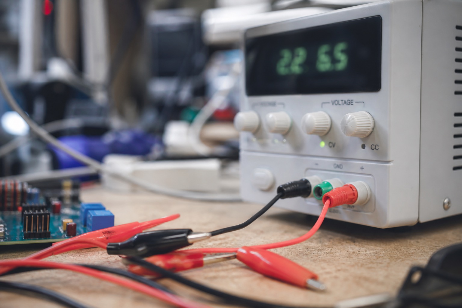
Current limiting on a bench supply sounds like a feature you add last. It is the feature that determines whether you blow up a prototype on a Tuesday night. On my LT3080 build, it also determined whether the supply oscillated at 40 kHz when the limit engaged — because voltage feedback and current feedback were sharing a loop I had not compensated separately.
Part 1 covers the motivation. Part 2 covers the LT3080 core. This note is about the current limit loop: architecture, compensation, and the mistakes that produced a sine wave on a supposed DC supply.
Answer first: separate loops, shared pass element
The stable approach:
- Voltage loop sets the LT3080 reference (via SET pin current / R_SET).
- Current loop overrides the voltage loop only when I_load × R_sense exceeds I_limit × R_sense_ref.
- Loops meet at a diode-OR (or precision OR-ing with op-amps) driving the SET pin, not inside the same feedback amplifier.
When both loops are wired through one op-amp without careful gain separation, crossing into current limit mode shifts the loop poles. That is when you get oscillation.
Current sensing topology
I used low-side sensing on the return path — not ideal for a general bench supply (ground lift issues when DUT is earth-referenced), but acceptable for my floating-output design.
Vout+ ---- load ---- Vout-
                      |
                   [0.1 Ω sense]
                      |
                     GND (supply local)
Sense amplifier: INA240A2 (gain = 50 V/V, bidirectional, 400 kHz BW). At 3 A:
V_sense = 3 A × 0.1 Ω = 300 mV V_out_amp = 300 mV × 50 = 15 V
That is too hot for a 5 V rail comparator. I added a divider (150 kΩ / 50 kΩ) to bring the 3 A full-scale signal to ~3.75 V for the limit comparator.
Current limit setpoint: 10-turn 5 kΩ pot on the comparator reference, calibrated with the Fluke in series.
The oscillation failure (rev 2)
Rev 2 used a single LM358 stage doing double duty:
- Non-inverting input: voltage set from panel pot
- Feedback: output voltage divider
- Current limit: pull-down on the same summing node via a PNP when sense voltage exceeded reference
It worked in CC mode at DC. On a pulsing load (ESP32 Wi-Fi transmit bursts), the output showed a clean 40 kHz sine at ~200 mV peak when current limit was near the edge.
Root cause (LTspice confirmed later):
- Voltage loop dominant pole: ~2 kHz (SET pin cap + internal regulator)
- Current limit engagement added a zero at ~8 kHz and moved the crossover above 30 kHz
- Phase margin went negative
Fix: split the loops.
Rev 3 architecture
                    +---[V loop op-amp]---+
                    |                     |
[SET pin network] <-+---[diode OR]--------+
                    |                     |
                    +---[I loop op-amp]---+
- V loop: MCP6002 (rail-to-rail out), crossover ~800 Hz, phase margin 55° (simulated)
- I loop: Same part, separate integrator, output through Schottky (BAT54) to OR node
- OR node: Diode OR to SET pin network; whichever loop demands lower voltage wins
When current limit is inactive, I loop output sits high (diode reverse biased). When load demands more than I_limit, I loop pulls SET down. V loop fights but loses because I loop has lower output impedance through the active diode.
Compensation values that worked
V loop integrator:
- R_in = 100 kΩ
- C_int = 100 nF (pole at ~16 Hz)
- R_f = 470 kΩ in parallel with C_int for DC gain limit
I loop ( faster — limit should engage without overshoot):
- R_in = 10 kΩ
- C_int = 22 nF
- No parallel R_f — I want this loop to slam when engaged
Critical: 100 nF from SET pin to OUT on each LT3080 (Analog Devices app note). Without it, the V loop picked up high-frequency peaking regardless of op-amp compensation.
Foldback vs constant-current
I implemented constant-current limiting only. Foldback (reducing current limit voltage as output collapses during a hard short) protects the pass transistors better but makes debugging some circuits miserable — a short looks like zero current and you chase the wrong problem.
Bench supply tradeoff: CC limit, panel LED that says "ILIM", and accept 15 W dissipation into a short at 5 V / 3 A until I turn the knob down.
For production hardware, I would add foldback below 1 V out. For bench use, visibility beats protection margin.
Measurements that matter
| Test | Result | Pass criteria |
|---|---|---|
| Short output at 5 V, I_limit = 1 A | 1.02 A ±30 mA, Vout ~0.3 V | Within 5% of set |
| Ramp load 0→2 A with I_limit = 1 A | Clean transition at 1 A, no oscillation | < 50 mV pp after 10 ms |
| Release from hard short | Recovery to 5 V in 8 ms | No overshoot > 200 mV |
| Wi-Fi pulsing load (ESP32) at I_limit edge | No 40 kHz artifact | Rev 3 pass; rev 2 fail |
The ESP32 test is the one that actually correlates with bench happiness. DC tests lie.
Interaction with paralleled LT3080s
When one device in the parallel bank current-folds internally (LT3080 has internal current limit ~1.2 A), the others pick up slack — unless your external limit is set below the per-device limit. I set external limit max at 3 A total, internal per-device at ~1.1 A each. External loop always wins first because it controls SET globally.
Mismatch scenario: one LT3080 dies shorted. External limit cannot detect per-device failure. Mitigation: fuse per device (0.5 A) on IN pins. I added these after a failed unit took the others with it.
Panel UX that saved debug time
- Red LED: ILIM active (comparator output, not software)
- Analog meter on output current: 1 mA resolution not required — trend visibility is
- Separate coarse/fine pots for voltage — the 10-turn for current limit only; voltage uses 1 kΩ coarse + 10 kΩ fine in series on the V loop reference
What I would do next
Add a current limit indication on scope trigger — a BNC out that goes high when ILIM engages. I have triggered on this twice to catch inrush problems on motor drivers.
Also considering e-fuse IC (TPS2660) downstream for DUT protection independent of the supply loop. Belt and suspenders.
Related reading
If you are bringing up multi-rail systems where limit behavior affects sequencing: power sequencing design notes. The loop separation lesson applies — do not share one feedback path and hope.

Manish Bookreader
Electronics enthusiast, Embedded Systems Expert, Linux/Networking programmer, and Software Engineer passionate about AI, electronics, books, and cooking.